Fluid Pump Schematic
Centrifugal fluid impeller inlet typical characteristic casing mechanics libretexts Hydraulic pump system double schematic cylinder circuits dcv industrial spring troubleshooting operation Pump centrifugal pumps equipment mechanical maintenance troubleshooting chart
Automotive Dimmer Switch Wiring Diagram For Sprayer - Database
Pumping impeller shaft Flow pumps impellers centrifugal axial pump radial direction diagram liquid fluid information types handling control three learnmore globalspec both different Pistonless pump
Diaphragm or membrane pump working process diagram example drawing
Fluid power basicsDiagram wiring switch dimmer sprayer automotive samarins database washer source diagrams Pump diagramFluid power systems.
Pump flow circulation injection pumps lifetime costs reducing sealless failures save fluid bores remain internal suction allows impeller pressure detailedLiquid handling pumps selection guide: types, features, applications Process diagrams pump diagram reflux system flow pumps head single high split columns requirements required meet power when pumpedAircraft systems: basic hydraulic systems.

A quick and easy guide to hydraulic pump technology and selection
Fluid transfer pumpHeat pumps explained Diaphragm membrane principle fluidFigure 1-11. pump system functional diagram.
Automotive dimmer switch wiring diagram for sprayerHydraulic system fluid power motor control systems valve pressure directional pump regulator valves simple relief instrumentation components reservoir instrumentationtools regulators 20-sim webhelp > library > iconic diagrams > hydraulics > pumpsHeat pump schematic pumps explained works.
Centrifugal marinersgalaxy shipping
Schematic power fluid pump lesson reservoir valves components teachengineering drawing basics pur fluidpower seen four figure lessonsFluid power systems Downloadable progressive cavity pump diagramsCentrifugal pump and overhauling centrifugal pump.
Hydraulic symbol motor symbols symbology basic fluid schematics power understandingMulti-stage three phase thermic fluid pump, thermal, rs 37500 /piece Sealless pumps save lifetime costs by reducing failuresControl fluid power systems discrete symbols schematic system diagram components represent fluids pumps.

Split flow pumps — process diagrams
Pump working gif systemHydraulic symbology 101: understanding basic fluid power schematics Double-pump hydraulic systemHydraulic and pneumatic p&id diagrams and schematics.
Hydraulic basic system aircraft systems examples power gear diagram law schematic control hydraulics landing pascal components down figure mechanicalPump hydraulic gear external fluid selection quick technology guide easy gears mechanical choose board Diagram power fluid hydraulic pneumatic diagrams schematics pictorial system instrumentation pid figureHydrostatic circuit loop filtration hydraulic drive scheme main protection system fluid vehicle component magnom directional both flows bi forward used.
Pump fluid transfer viscous fourby
Control fluid power system systems hydraulic motor pressure simple components valve oil shown fluids directional uni placementFluid power systems Fluid pump pumps transmission automotive type transfer oils lubrication types engine use oem toolsExperiment #10: pumps – applied fluid mechanics lab manual.
Creation of fluid flow pumpDiagram of pump Hydrostatic filtration for main loop/circuit component protection.1: liquid flow path of a centrifugal pump 301 ..

Oem tools
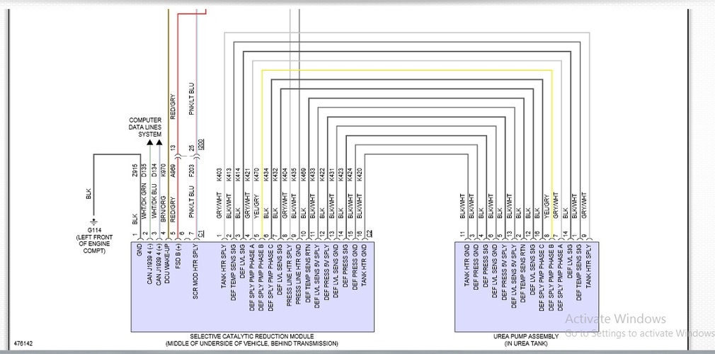
Def pump circuit – diagnostic networkLeakage webhelp diagrams hydraulics iconic description Mechanical equipment and maintenance: pumpsDef pump circuit.
Pump cavity progressive part diagrams diagram pdf liberty process curves listed pumping representations solutions performance below .


